Contribute the improving of production efficieny by offering our standardized items.
![]()
![]()
E-9659H
![]()
| Type | Order No. | No. | Outer Diameter |
Pin Diameter |
Overall diameter |
weight (kg) |
Drawing | Product BOX |
CAD | Production | Stock Status |
|---|---|---|---|---|---|---|---|---|---|---|---|
| Locating pin | 129619 | QLH26DRP | 60 | 26 | 45 | 0.4 | View | Add | DATA | Stock Item | Stock〇 |
| Locating pin | 129620 | QLH32DRP | 72 | 32 | 51 | 0.6 | View | Add | DATA | Stock Item | Stock△ |
| Locating pin | 129621 | QLH40DRP | 88 | 40 | 61.5 | 1 | View | Add | DATA | Stock Item | Stock〇 |
| Locating pin | 129622 | QLH48DRP | 105 | 48 | 74 | 1.8 | View | Add | DATA | Stock Item | Stock〇 |
| Dia. Pin | 129623 | QLH26DDP | 60 | 26 | 45 | 0.4 | View | Add | DATA | Stock Item | Stock〇 |
| Dia. Pin | 129624 | QLH32DDP | 72 | 32 | 51 | 0.6 | View | Add | DATA | Stock Item | Stock〇 |
| Dia. Pin | 129625 | QLH40DDP | 88 | 40 | 61.5 | 1 | View | Add | DATA | Stock Item | Stock〇 |
| Dia. Pin | 129626 | QLH48DDP | 105 | 48 | 74 | 1.8 | View | Add | DATA | Stock Item | Stock〇 |
| Clamping pin | 129627 | QLH26DCP | 60 | 24 | 45 | 0.4 | View | Add | DATA | Stock Item | Stock〇 |
| Clamping pin | 129628 | QLH32DCP | 72 | 30 | 51 | 0.6 | View | Add | DATA | Stock Item | Stock〇 |
| Clamping pin | 129629 | QLH40DCP | 88 | 37 | 61.5 | 1 | View | Add | DATA | Stock Item | Stock△ |
| Clamping pin | 129630 | QLH48DCP | 105 | 45 | 74 | 1.8 | View | Add | DATA | Stock Item | Stock〇 |
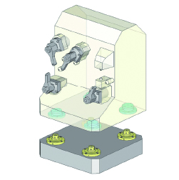
Quickest jig exchanges on Horizontal machining centers
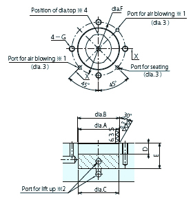 |
※Dia.pin’s top position and tapped hole are as per drawing, so machine tapped holes and port holes to follow the direction of dia. |
※1.There are 2 air-blowing holes, so take use of one.
※2.Lift up port must be within area.
※3.O-ring contacted surface must be without burrs(roughness 6.3S or under)
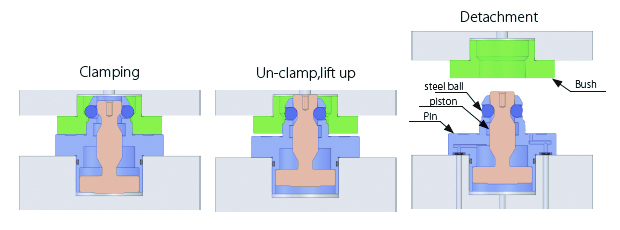
| Type | Hydraulic type, double action | ||||
| Drive system | Clamping | Hydraulic | |||
| Un-clamp | |||||
| № | QLH26D*P | QLH32D*P | QLH40D*P | QLH48D*P | |
| Clamping force (kN) at 0.5MPa | 3 | 7 | 10 | 16 | |
| Lift up force(kN) at 0.5MPa | 1.5 | 2.7 | 4 | 6 | |
| Clamping stroke(mm) | 4.5 | 5 | 6 | 7 | |
| Lift-up amount (mm) | 1 | ||||
| Cylinder volume(cm3) | Clamping side | 0.7 | 1.5 | 2.6 | 4.3 |
| Un-clamp side | 1.4 | 2.7 | 4.8 | 8.6 | |
| Max. working pressure(MPa) | 5 | ||||
| Min. working pressure(MPa) | 2 | ||||
| Proof pressure(MPa) | 7 | ||||
| Recommended air blowing pressure(MPa) | 0.5 | ||||
| Fluid | Dry air | ||||
| Ambient temperature (℃) | 0~65 | ||||
| Weight(kg) | 0.4 | 0.6 | 1.0 | 1.8 | |


Enter Model No./Product name/relative keywords
Product information can be recorded temporarily while browsing the page
![]()
Wakasugi-cho 25, Gifu-shi, Gifu 500-8743
TEL.058-273-6521 FAX.058-278-0220
![]()
Copyright © NABEYA Co.,Ltd. All Rights Reserved.