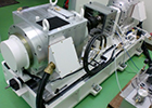
Per second set up!
Q-lock elements make it possible to have higher accuracy of Jig(location repeatability within 3 microns) and quick clamping.
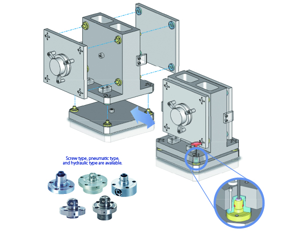
●Reference examples.(in case of screw type)
※ The above shows the usages for screw type
Basic lay-out
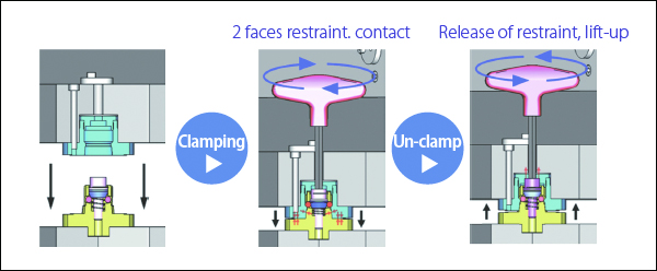
Q-Lock Elements How to use screw, hydraulic, pneumatic type properly.
●Level of diffi culties on Jig designing and Arrangement

●Clamping Force

●Initial Cost

●Jig Exchanging Times

| Usages suitable for screw type | ・In case that initial cost muct be lower ・In case of retrofi t jigs on machinery. ・In case of less exchanging jigs. |
| Usages suitable for hydraulic type | ・In case of much exchanging jigs ・In case of operations at night and on holidays. ・In case of larger workpieces. |
| Usages suitable for pneumatic type | ・In case of much exchanging jigs. ・In case of operations at night and on holidays. ・In case of smaller workpieces. |
Improvement for machine operating rate!!
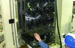
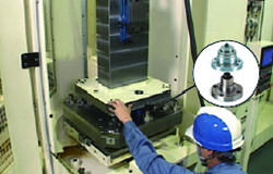
●By simple& quick & accurate Jig loading, machine operation rate become much higher!
 |
 |
|
| Without Q-lock elements | With Q-lock elements | |
| Centering is needed!! | No need to check accuracy!! | |
| Centering by experienced operator is needed for each loading. | Repeatability of 3micron by 2 faces restraint system. No need to check ccentering of jigs repeatedly. |
Shorten the jig arrangement time!
●Jig arrangement time can be shortened by 50-70%!!
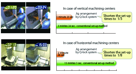
Workability, machine operating rate can be improved by off -line set up!!
●For large machining centers, machine operating rate can be improved by off -line jig set-up.

Q-lock elements are being used as followings.
●Change of Tooling blocks
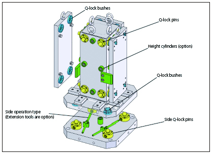
●Change of jig plates on Cradle type Jig
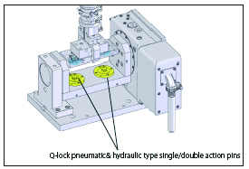
●Special jig exchanges for 5 axis machining centers or Rotary table.
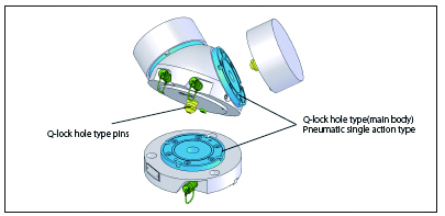
●Exchange of large plates
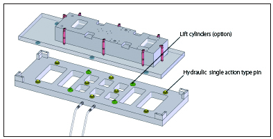
●Exchange of small jigs
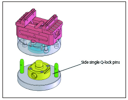
●Exchange of small workpieces ●Exchange of large workpieces
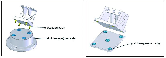
Mounting method
Verifi cation of used Pins and Bushes
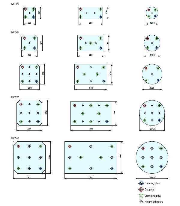
There are 3 kinds of pins on Q-lock elements, locating pins, dia.pins and clamping pins.
Characteristics must be checked for each one before using.
| ●Locating pins(RP) being used for positioning on XY axis and Z axis + tightening. ●Dia.pins(DP) being used for phase determination on rotating directions and positioning on Z axis and tightening. ●Clamping pins(CP) being used for positioning on Z axis and tightening. ●Locating bushes(RB) must be used for locating and dia.pins. Clamping bushes(CB) must be used for clamping pins. |
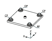 |
※Jig plates must be carried without inclinations to avoid the damages on Q-lock body. Use of rough guides is recommended.
Machining of mating components and mounting method.
1.Hole dimensions (for fi xing pin and bush) must be machined according to catalogue and manuals.
2.2.Pitches of pin-holes and bush holes on base and jig plates must be machined within +-0.01 (refer to drawing 1)
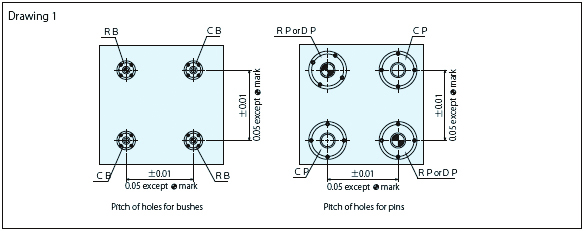
3. If holes for bushes on jig plates can not be machined within +- 0.01 following processes must be taken.
 |
 |
| ①Holes for bushes must be machined with adjustment allowances on pitch. | ②Pin must be fi xed on base plates. |
 |
 |
| ③Bush must be fi xed on jig plates. Bush mounting bolts must be clamped temporarily. | ④Temporary tightened bushes on jig plate must be inserted into pin on base plates and clamping bolts then tighten bush mounting bolts. |


