Contribute the improving of production efficieny by offering our standardized items.
![]()
![]()
E-9475
![]()
| Order No. |
No. | Jaw Width |
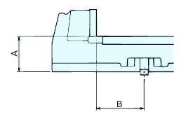
Jaw Depth |
Jaw Opening |
Standard Guide Block Width |
Clamping Force kN |
Weight (kg) |
Drawing | Product BOX |
CAD | Production | Stock Status |
|---|---|---|---|---|---|---|---|---|---|---|---|---|
| 967819 | LTH3P150S | 156 | 57 | 300 | 18 | 40 | 41 | View | Add | DATA | Stock Item | Contact |
| 968833 (Matched Specification) |
LTH3P150SG | 156 | 57 | 300 | 18 | 40 | 41 | View | Add | DATA | × | Contact |
| Order No. |
№ | CompatiBle Models | Drawing | Product BOX |
CAD | Production | Stock Status |
|---|---|---|---|---|---|---|---|
| 969390 | LTH3P150S-ASSY | LTH3P150S | View | Add | DATA | × | Contact |
|
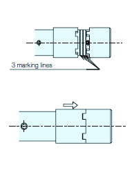
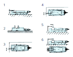
(1) Clamping method by hydraulic pressure ・With the matching parts of the switching collar and socket separated, rotate the handle in the clockwise direction.
・The clamping stroke by hydraulic pressure is approximately 1.8 mm. (2) Clamping method by screw ・Slide the switching collar towards the socket side, and with the switching collar and socket interlocked, rotate the handle in the clockwise direction. (3) Combination of clamping by screw and clamping by hydraulic pressure ・When clamping workpieces that deform easily and workpieces where the workpiece surface is a cast surface, perform clamping using the screw and then perform clamping using hydraulic pressure. |
 |
| Order multi-jaw specification products (suffix G) When ordering, specify the groove width of the machine you are using. Can only be manufactured when newly purchasing Matched specification products. |
 |
|
 |
||||||||||||||||||||||||||||||||
 E-9275B/MACHINE VISE SERIES ACCESSORIES
 E-9275B/MACHINE VISE SERIES ACCESSORIES
 E-9275B/
 E-9275B/MACHINE VISE SERIES ACCESSORIES
 E-9275B/

Enter Model No./Product name/relative keywords
Product information can be recorded temporarily while browsing the page
![]()
Wakasugi-cho 25, Gifu-shi, Gifu 500-8743
TEL.058-273-6521 FAX.058-278-0220
![]()
Copyright © NABEYA Co.,Ltd. All Rights Reserved.